DLT-4

Load Cell Amplifier

DLT-4

Load Cell Amplifier

The DLT-4 Digital Load Cell Amplifier is a DIN rail mount load cell amplifier designed for accurate and stable industrial weighing applications. It converts low-level millivolt signals from strain gauge load cells into standard analog outputs such as 0 to 10 VDC and 4 to 20 mA for seamless integration with PLCs, HMIs, and PCs. Ideal for batching, bagging, dosing, tank and silo weighing, filling, and weighbridge systems, the DLT-4 ensures reliable performance. All calibration and settings are easily managed through trimpot adjustments.

Product Type

Digital Load Cell Amplifier

Usage

Industrial Automation, Material Testing, Check weighing, Hopper & Batching Systems, Silo & Tank Weighing

Material

Din Rain Mountable Box Enclosure

Output

4-20mA/0-10V Analog Output

Theory

Load Cell Amplifier

Calibration

Calibration can be done through setting via Trim Port setting

Power Supply
24 VDC
Analog Input Range
-20mV to +20mV
Analog
16-bit output (0-10VDC or 4-20 mA)
Display
No Display (Only Trim Port for Zero & Span setting)
Load Cell Support
Supports up to 4 load cells (700 Ohms) connected via junction box with 3.3 VDC excitation
Dimensions
Approximately 100 mm (height) x 113.5 mm (depth) x 22.5 mm (width).

Related Products

FAQs

frequently asked questions

01. What is the fundamental role of a Load Indicator in a weighing system?

A Load Indicator (or Digital Weight Indicator) is the primary user interface and digital core of the weighing system. Its main roles are:

  • > Power Supply: It provides the stable excitation voltage (power) to the load cell.
  • > Signal Conversion: It receives the raw, micro-voltage (mV) signal from the load cell, amplifies it, and converts it into a digital value.
  • > Display: It displays the final calculated weight in a readable format (kg, T, N) to the operator.
  • > Calibration: It stores the system’s calibration parameters (zero, span, decimal points, capacity).
  • > Communication: It communicates with devices such as HMI, PLC, PC, other devices via modbus RTU RS-485.
02. How does a Load Controller differ from a basic Load Indicator?

A Load Controller (or Process Controller) is essentially an indicator with additional control functionality used in automation:

  • > Indicator: It performs all the basic functions of a standard indicator (display, power, signal conversion).
  • > Control Logic: It contains built-in software or programming for specific applications like batching, filling, mixing, or checkweighing.
  • > Outputs: It features discrete I/O (Input/Output) relays or ports that can be used to control external devices (e.g., stopping a conveyor, opening a valve, or triggering an alarm) based on weight set points.
03. What is a Load Cell Amplifier (or Transmitter), and when is it necessary?

A Load Cell Amplifier (or Transmitter) is a specialized device used to prepare the load cell signal for communication with industrial controllers like PLCs (Programmable Logic Controllers).6

  • > Function: It takes the tiny mV signal and converts it into a standard, robust industrial signal, most commonly 4-20mA or 0-10VDC.
  • > Necessity: Standard industrial controllers (PLCs) cannot directly read the load cell’s raw mVoutput. The amplifier makes the signal less susceptible to electrical noise and voltage drop over long distances, ensuring the PLC receives an accurate, proportional weight reading.
04. Why is the 4-20mA signal commonly preferred in industrial applications?

The 4-20mA current loop is the most robust standard for transmitting analog signals in harsh industrial environments for two key reasons:

  • > Noise Immunity: Current signals are far less susceptible to electromagnetic interference (noise) over long cable runs than voltage signals.
  • > Live Zero: The 4mA value represents the zero output (unloaded state). If the signal drops to 0mA (or close to it), the system immediately detects a broken wire or power failure, providing a built-in error detection mechanism.
05. How do multiple load cells connect to a single indicator/controller?

When a system uses multiple load cells (e.g., a four-load cell tank system), they are connected using a Junction Box (J-Box).

  1. Wiring: The cables from all individual load cells run into the J-Box.
  2. Trimming: The J-Box contains terminal blocks and typically trimming resistors to electronically adjust the output of each load cell (called corner trimming or balance adjustment).
  3. Summation: The signals are electrically summed together within the J-Box.
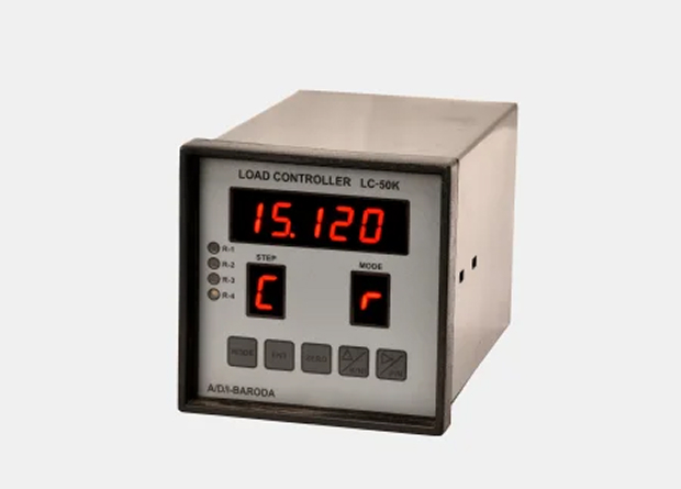
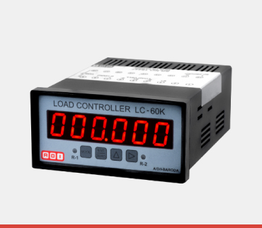
  4. Single Output: A single main cable then runs from the J-Box to the Indicator or Controller, providing one combined weight signal.