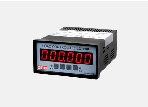
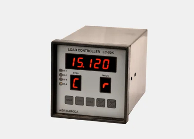
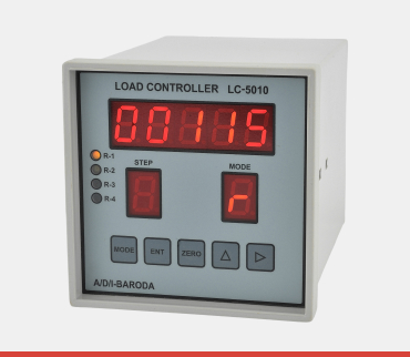
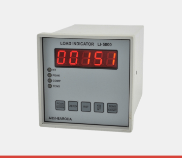
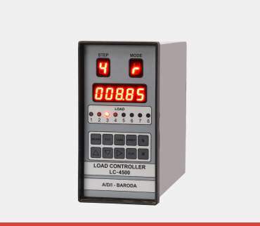
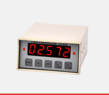
Digital Load Cell Controller
Industrial Automation, Material Testing, Check weighing, Hopper & Batching Systems, Silo & Tank Weighing
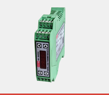
Mild Steel Chasis with ABS cover
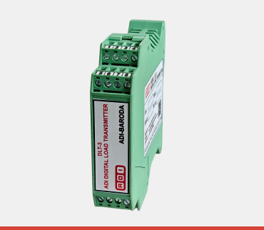
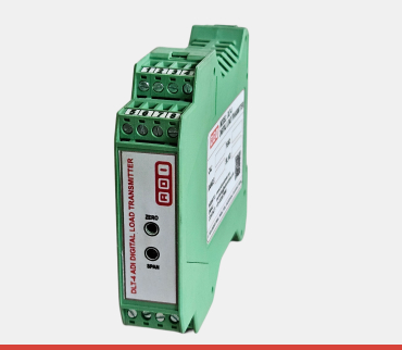
RS485, Modbus RTU, Relay Output, Analog Output (0 to 10 VDC / 4 to 20 mA)
Calibration can be done through setting via keypad & Modbus RS-485
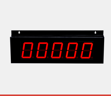
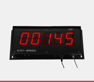
6-digit red LED display with auto-polarity
Selectable between Kgf and Newton
LED indicators for Relay 1 (R-1) and Relay 2 (R-2)
Can handle up to 8 load cells
Provides approximately 3.3 VDC
Adjustable settings up to 50,000 or 100,000 counts
Standard calibration features with an option for 20-point calibration
2 Relays with 1 NO (Normally Open) contact provided for logically set alarm and trip functions
RS485 Modbus RTU protocol for communication with PLCs, HMIs, and computers
Includes input start signal for batching processes, remote reset, and remote display output
Universal SMPS supporting 90-265 VAC, 50/60 Hz
Advanced intelligent microcontroller and Delta Sigma ADC-based design for drift-free, stable, and noise-immune output
Bezel Size: 96mm (w) x 48mm (h).