ART-351

Crane Load Cell

Home / Products / Load Cells / ART-351

ART-351

Crane Load Cell

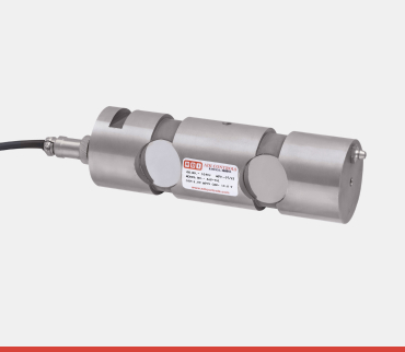
ADI ART-351 rope tension load cell is a specialized sensor designed to measure the tensile force (pulling force) or tension applied to a cable, wire rope, or synthetic fiber rope. This is a portable or permanently mounted device that clamps onto the rope without cutting or disconnecting it. It typically uses three or more sheaves/rollers mounted on a frame. The center sheave is connected to a compression or shear load cell (often a load pin or small canister cell). The outer sheaves deflect the rope slightly, and the force created by this deflection is measured by the load cell. The force reading is then converted back (via calibration based on the rope’s diameter and the deflection geometry) to the actual tension in the straight section of the rope. Crane boom cable tension checks, elevator maintenance, winch line monitoring, and structural guy wire inspection. Also known as model 30510

Product Type

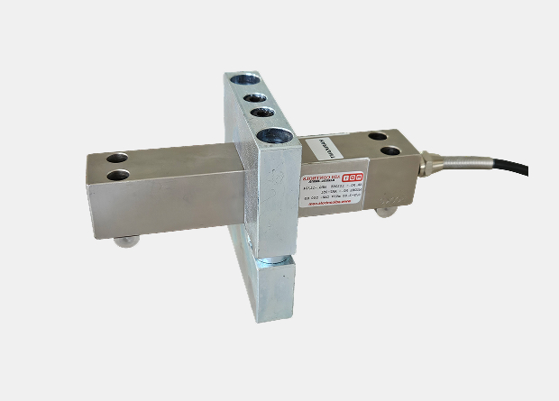
Single Point Aluminium Load Cell

Usage

Table top scales, Counting and postal scales, Check weighers.

Material

Aluminium

Output

 Analog Sensor

Theory

Resistance Sensor

Compensated Temperature

10 To 60 Celsius (oC)

Rated capacity (Kgf)

0.5, 1, 2

Excitation Voltage

10 V DC – Maximum 15 V DC

Rated Output

1 mV/V

Non – Linearity

< ± 5.0 % FSO for range up to 20%

± 2.0 % FSO for range above 20%

Hysteresis

< ± 0.1 % FSO(Full scale Output)

Non-Repeatability

< ± 0.1 % FSO

Creep error (30 minutes)

< ± 0.03 % FSO< +/- 0.03 % of FSO

Zero Output

± 1.0 % FSO

Input Resistanc e

390 Ohms

Output Resistance

350 Ohms

Insulation Resistance

>1000 Mega Ohms

Safe Overload

150 % of Rated Capacity

Ultimate Overload

300 % of Rated Capacity200 % of Rated Capacity

Temperature
Compensated Range

0 to 60° C

Temperature Effect on
Output

< 0.005 % FSO/° C

Temperature Effect on
Zero

< 0.005 % FSO/° C

Deflection

< 0.5 mm at FSO

Finish & Construction

Electroless Nickel Plated Tool Steel.
Stainless Steel Available optionally.

Environment Protection

IP 65

Industries

EOT CRANE INDUSTRIES
HVAC System
LABORATORY TESTING
Heat Treatment

Related Products

FAQs

frequently asked questions

01. What is a Load Pin Load Cell and how does it function in a clevis application?

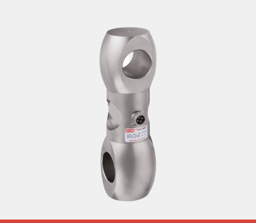
A Load Pin Load Cell is a specialized force sensor designed to measure shear forces by directly replacing the inert mechanical pins (like clevis pins, shear pins, or axle pins) in machinery and lifting gear.

  • > Function: When installed in a clevis, pulley, or sheave system, the pin measures the shear stress exerted by the load on the inner portion of the pin.
  • > Key Advantage: It allows you to transform existing, permanently mounted machinery (like cranes, winches, hoists, and cable anchors) into a high accuracy weighing or force monitoring system without complex structural modifications.
02. Where are Load Pins most frequently used for force monitoring?

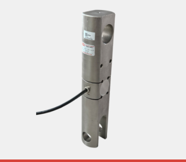
Load Pins are ideal for fixed installations where continuous, reliable force feedback is needed, often in environments where other load cell types are impractical.

  • > Hoisting and Crane Machinery: Replacing pins in hoist shackles, equalizing sheaves, or boom foot pins for continuous overload protection and load monitoring.
  • > Mooring and Anchoring: Measuring tension in marine mooring lines, anchors, and tow hooks.
  • > Suspended Weighing: Used in block and tackle systems, or in pulley systems where wire rope tension needs to be monitored.
  • > Structural Monitoring: Measuring tension in cable stays or structural supports.
03. How do I select the correct Load Pin dimensions and capacity?

Selecting the correct load pin is critical, as it must function perfectly as a mechanical component while providing accurate electronic output.

  • > Dimensions: The pin’s diameter and effective length (the distance between the bearing points) must exactly match the pin it is replacing. Any dimensional mismatch can compromise the mechanical integrity of the lifting point.
  • > Capacity: The rated capacity of the Load Pin must match or exceed the Safe Working Load (SWL) of the specific lifting point it is installed into, using a standard safety factor (typically 150% to 200%) of the maximum expected load). Never install a pin with a lower capacity than the lifting point’s SWL.
04. Why is a Load Pin often supplied with a retaining plate/collar?

The retaining plate or collar serves two essential functions:

  1. Anti-Rotation: It prevents the load pin from rotating within the bore during operation. Rotation would cause damage to the wiring and introduce inaccurate readings, as the strain gauges are aligned to measure the force in a specific direction.
  2. Axial Restraint: It physically holds the load pin securely in its bore, preventing it from slipping out under load or vibration, which is a critical safety feature in lifting applications.

Note: Unlike standard clevis pins, Load Pins must be installed with the retaining feature properly secured and the force-sensing axis correctly aligned (typically indicated by the cable exit).

05. What are the sealing requirements (IP Rating) and cable protection needs for Load Pin Load Cells?

Given their installation location—often exposed to the elements, moisture, and potential abrasion—robust protection is mandatory:

  • IP Rating: Load Pins should have a rating of at least IP67 (protected against temporary immersion) or IP68 (hermetically sealed/submersible) to resist water, high humidity, and dust ingress common in port, offshore, or construction environments.
  • Cable Protection: The signal cable exiting the pin is its most vulnerable point. The cable gland must be highly robust, and the cable itself should be routed using external conduit, cable glands, or protective sheathing to prevent mechanical damage from abrasion, pinching, or accidental snagging.