AMT-511

Multi Axis Load Cell

Home / Products / Load Cells / AMT-511

AMT-511

Multi Axis Load Cell

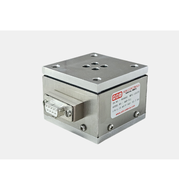
ADI AMT-511 multi-axis load cell (also known as a multi-component force sensor or 6-axis load cell) is a specialized transducer capable of measuring forces and moments (torques) simultaneously along or around multiple independent axes. Unlike standard single-axis load cells, these sensors can measure up to six components of force. Forces along the X, Y, and Z axes can be measured. The sensor’s body is intricately machined, often featuring a cruciform, spoke, or web design, to decouple the different load components. Since the application of force on one axis often induces a small signal on others (known as crosstalk), a complex mathematical calibration matrix (or decoupling matrix) is essential to separate the raw signals and provide accurate, independent measurements for all six components.

Product Type

Single Point Aluminium Load Cell

Usage

Table top scales, Counting and postal scales, Check weighers.

Material

Aluminium

Output

 Analog Sensor

Theory

Resistance Sensor

Compensated Temperature

10 To 60 Celsius (oC)

Rated capacity (Kgf)

20, 30

Excitation Voltage

10 VDC-Maximum 15 VDC

Rated Output

1.2 mV/V in X & Y axis. 1.4 mV/V for Z axis

Non – Linearity

<±0.5 % FSO (Full scale Output)

Hysteresis

<± 0.5 % FS0

Non-Repeatability

<± 0.2 % FS0

Creep error (30 minutes)

<+ 0.05 % FS0

Zero Output

± 1.0 % FSO

Bridge Resistance

350 ± 10 Ohms

Output Resistance

700 +/- 5 Ohms

Insulation Resistance

> 2000 Mega Ohms

Temperature
Compensated Range

10° to 60° C

Temperature Effect at Full Load

< 0.05 % FSO/° C

Temperature Effect at Zero Load

< 0.05 % FSO/° C

Side Load Allowed

50 % of Rated Capacity

Finish & Construction

Aluminium

Environment Protection

IP 65

Industries

Robotics
FAQs

frequently asked questions

01. What is a Multi-Axis Load Cell and why are they used?

A Multi-Axis Load Cell is an advanced force sensor designed to measure multiple independent force and/or torque components simultaneously.

  • > Capability: Unlike traditional load cells that only measure force along a single axis (e.g. F z), a multi-axis cell can measure forces along the X, Y, and Z axes (F x, F y, F z) and/or the moments (torques) around those axes (M x, M y, M z), typically providing up to 6 Degrees of Freedom (DoF) measurement.
  • > Why Use Them? They are essential when the applied load is complex and non-axial, requiring a complete, three-dimensional understanding of the forces acting on a structure or object.
02. What are the key applications for Multi-Axis Load Cells?

These high-precision sensors are used in complex, high-tech environments where a holistic view of force and torque is necessary.

  • > Robotics and Automation: Measuring forces at the “end-of-arm tooling” (robot gripper) to provide haptic feedback, prevent damage, and control delicate manipulation tasks.
  • > Aerospace and Automotive Testing: Used in wind tunnels, tire testing, suspension testing, and flight control surface analysis to capture complex aerodynamic forces and torques.
  • > Biomechanics: Measuring ground reaction forces, joint forces, and gait analysis in medical and sports research.
  • > Ergonomics and HMI (Human-Machine Interface): Measuring the push, pull, and twist forces exerted by human operators on joysticks, steering wheels, or control panels.
03. What is the concept of "Crosstalk" and why is it important for Multi-Axis Load Cells?

Crosstalk (or cross-axis sensitivity) refers to the unavoidable, small influence that a load applied to one axis (e.g. F x) has on the measured output of another axis (e.g. F y or F z).

  • > Importance: In an ideal sensor, a load on F x would only register on the F x channel. Since mechanical structures are never perfect, some crosstalk exists.
  • > Correction: High-quality multi-axis load cells, like those supplied by Adi Controls, require a complex Calibration Matrix (often a 6 x 6 matrix for a 6-axis sensor) to mathematically separate the output signals. This matrix is applied in the measurement electronics to ensure the reported forces and moments are accurate and independent of each other.
04. How do I select the correct capacity for a Multi-Axis Load Cell?

Selecting the capacity is more complex than for a single-axis cell, as multiple forces must be considered simultaneously.

  1. Define Maximum Loads: Determine the maximum expected force or moment for each of the axes (F x max, F y max, M z max, etc.).
  2. Safety Margin: Apply a significant safety margin (e.g.150 to 200%) to each axis’s maximum expected load to account for sudden impacts, overloads, and dynamic spikes.
  3. Check Combined Load: While a cell might be rated for 100 N on F x and 100 N on F y, its maximum combined load capacity may be lower. Always verify the manufacturer’s specifications for the safe operating range when multiple axes are loaded simultaneously.
05. What specialized Electronics/Data Acquisition is required for these sensors?

Due to the complexity of the output, Multi-Axis Load Cells require specialized hardware and software:

  • > Multiple Channels: The cell outputs multiple independent signals (e.g., six voltage signals for a 6-axis sensor) simultaneously.
  • > Signal Conditioning: Each signal must be amplified and conditioned individually.
  • > Matrix Calculation: The data acquisition (DAQ) system or amplifier must be capable of applying the unique Crosstalk Calibration Matrix supplied with the cell. This mathematical calculation converts the raw sensor outputs into the true, corrected, and independent force and moment values (F x, F y, M z, etc.). Standard single-channel amplifiers cannot be used.