A pressure transducer rarely fails without warning. Most faults first appear as a drifting value, a jumpy signal, or a reading stuck at zero.
In our experience, many sensors reported as faulty turn out to be working fine. The real cause sits in the wiring, the power supply, or the way the sensor was installed. This guide covers the seven problems our engineers see most often on hydraulic, pneumatic, and process lines, with fixes your maintenance team can try before ordering a replacement.
Knowing the pressure transducer working principle makes fault finding much faster. Inside the sensor, a thin diaphragm of stainless steel or silicon flexes when pressure acts on it. Tiny resistors bonded to that diaphragm change their resistance as it bends, which is known as the piezoresistive effect.
These resistors are wired as a Wheatstone bridge. The bridge produces a small millivolt signal, and onboard electronics amplify it into a standard output such as 4 to 20 mA or 0 to 10 V. Every reading depends on the diaphragm, the bridge, the electronics and the supply feeding them. When a value looks wrong, one of these links is usually the reason.
1. No output or a reading stuck at zero
Check the supply voltage at the sensor terminals, not at the panel. A 24 V loop that measures 17 V at the far end may not power the device properly. Look for reversed polarity, a blown fuse or a loose terminal. On a 4 to 20 mA loop, a current close to 0 mA points to an open circuit.
2. Zero drift over time
A sensor showing 0.3 bar on a fully vented line has drifted. Temperature swings, ageing of the sensing element and stress from an over tightened fitting all play a part. Vent the line, note the offset and rezero through the indicator or PLC. If the drift returns within weeks, the diaphragm may be fatigued.
3. Noisy or fluctuating readings
Jumping values usually come from electrical noise rather than real pressure changes. Route the signal cable away from VFD and motor power cables. Use shielded cable, grounded at one end only. Where pump pulsation causes the swing, a snubber or a small damping setting in the controller will smooth it.
4. Reading higher or lower than the reference gauge
Compare the sensor against a calibrated test gauge at two or three points. A constant offset suggests a zero error. An error that grows with pressure points to a span problem. Also confirm the indicator scaling, because a 0 to 10 bar sensor scaled as 0 to 16 bar will read wrong across the whole range.
5. Damage from overpressure or pressure spikes
Water hammer and sudden valve closures can push peaks far beyond the rated range. The result is a permanently shifted zero or a dead sensor. Select a range where normal working pressure sits around 50 to 75 percent of full scale. Fit a snubber on lines with fast closing valves.
6. Moisture inside the connector
Condensation in the cable gland causes slow, wandering readings and eventual failure. Check that the connector seal is seated and the cable enters from below so water drains away. An IP65 housing suits most indoor plant areas, while wash-down zones need a higher protection rating.
7. Wrong pressure reference
A gauge sensor measures against atmosphere through a small vent. If that vent is blocked, readings can shift with the weather. An absolute sensor fitted where gauge pressure is expected will read about 1 bar high. Confirm the reference type on the label before chasing other faults.
If a fix restores a stable, accurate reading, keep the sensor in service and log the event. Recalibrate critical loops at least once a year. Replace the unit when drift keeps returning, the diaphragm shows physical damage or the output no longer rises in a straight line with pressure.
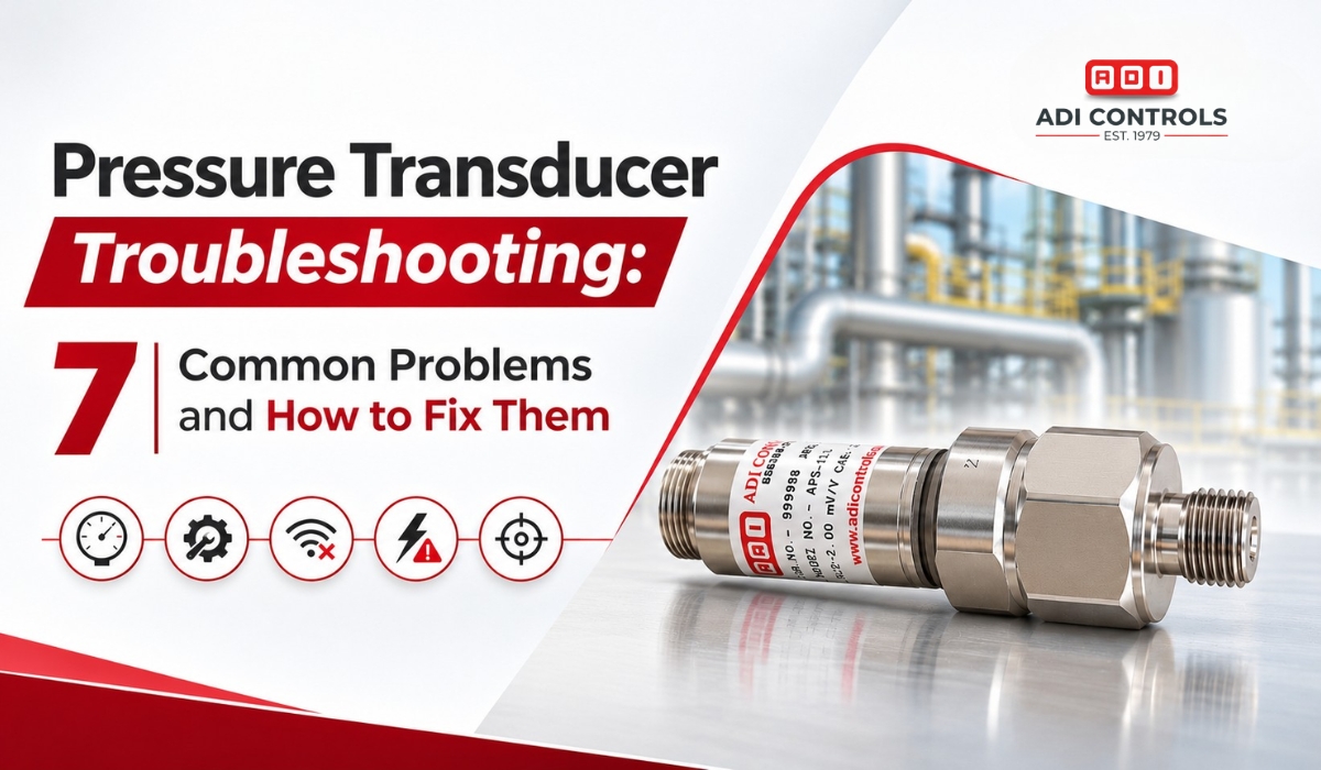
The APT-411 pressure transducer from ADI Controls uses a stainless steel sensing body for liquid and gas service, and it can be customized to your application. You can compare options across our pressure transducer range. Facing a fault this guide does not cover? Share your application details with our team and our engineers in Vadodara will help you fix the sensor you have or choose the right one.
A pressure transducer uses a diaphragm that flexes under pressure. Resistors bonded to it change resistance, and a Wheatstone bridge turns that change into a millivolt signal. Built in electronics then convert it into a 4 to 20 mA or 0 to 10 V output.
Measure the supply voltage at the sensor terminals first. With the line vented, the output should read about 4 mA or 0 V. Apply a known pressure and confirm the output rises in proportion. No change points to a wiring or sensor fault.
Most industrial users calibrate once a year. Critical safety loops, lines with frequent pressure spikes and sensors in hot areas may need checks every six months. Keep a calibration log so you can spot drift trends before they affect production.
Pick a range where normal operating pressure sits between 50 and 75 percent of full scale. This leaves headroom for spikes while keeping good resolution. Also confirm the gauge or absolute reference, process connection, output signal and compatibility with your media.
WhatsApp us