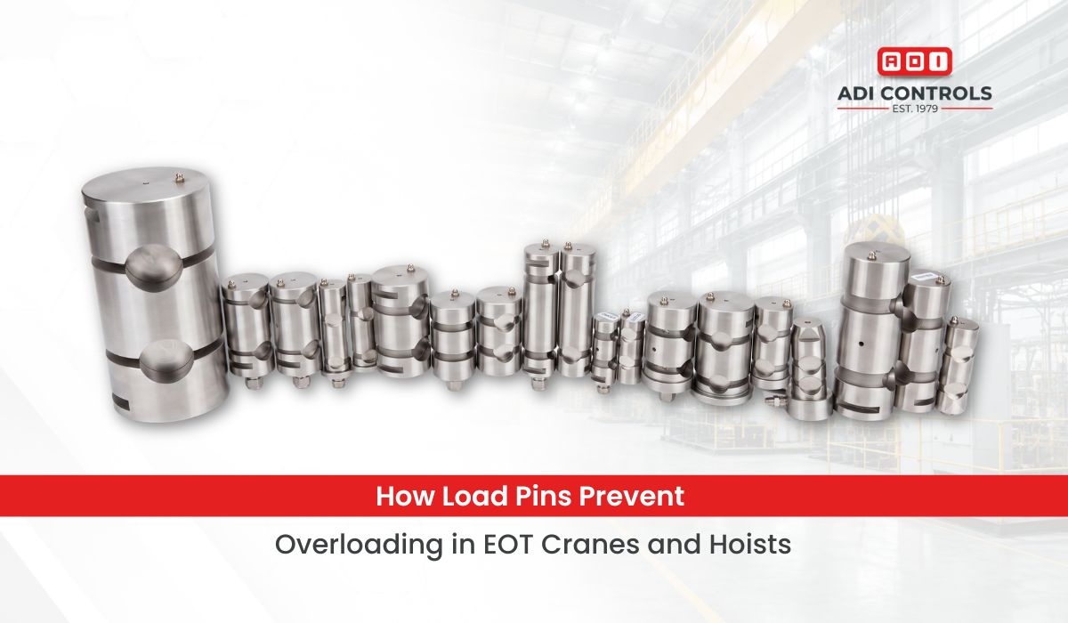
Pins serve as load-bearing connections in cranes, hoists, shackles, winches and industrial machinery. A standard pin transfers force between mechanical components. An instrumented pin can perform the same structural function while measuring the applied force.
Terms such as clevis pin, standard load pin and pin type force sensor are often used interchangeably. However, their purpose and measurement capabilities are not always the same.
Understanding these differences helps engineers select a suitable sensor for overload protection, lifting safety and industrial force monitoring.
A standard mechanical pin is a solid cylindrical component used to connect two or more machine parts. It may work as an axle, pivot, hinge or joint.
Common applications include:
• Clevis joints
• Crane mechanisms
• Hydraulic cylinders
• Shackles
• Pulleys and sheaves
• Hoists and winches
• Construction machinery
• Material-handling equipment
A mechanical pin supports the applied load but does not generate a measurement signal. The equipment requires a separate sensor if the operator needs real-time force data or overload protection.
A clevis pin passes through the aligned holes of a U-shaped clevis and the component positioned between its arms. It creates a strong connection while allowing limited movement around the joint.
A conventional clevis pin is a mechanical component only. It does not measure force.
Manufacturers can replace it with an instrumented pin designed to match the original dimensions. The replacement pin contains strain gauges and provides an electrical signal proportional to the applied force.
“Clevis” therefore describes the joint configuration. It does not automatically mean that the pin includes force-measurement technology.
A pin type force sensor is a cylindrical transducer installed in place of a structural pin. It supports the connection while measuring the force transmitted through the joint.
Precision-machined sensing sections inside the pin contain bonded strain gauges. When force acts on the pin, these sections deform by a microscopic amount. The strain gauges detect this change and produce an electrical output.
The signal can be connected to:
• A digital indicator
• A load controller
• An overload alarm
• A signal transmitter
• A PLC or HMI
• A data-acquisition system
• A wireless monitoring device
This integrated arrangement provides force measurement without adding a bulky external sensor or making major changes to the machine.
ADI Controls manufactures industrial load cells and force sensors for lifting, weighing, testing and automation applications.
Feature | Standard mechanical pin | Pin type force sensor |
Main purpose | Connects mechanical components | Connects components and measures force |
Electrical output | No | Yes |
Strain gauges | No | Integrated into the pin |
Overload monitoring | Not available | Available with suitable electronics |
PLC integration | No | Possible through a controller or transmitter |
Custom dimensions | Sometimes | Commonly required |
Calibration | Not required | Required |
Typical use | General machine joints | Cranes, hoists, winches and monitored joints |
A standard pin is suitable when the machine only needs a mechanical connection. A force measuring pin is required when the system must measure, record or control the force acting through that connection.
Most instrumented pins use shear-based measurement.
The load acts between the supported and loaded sections of the pin. This creates shear stress in specific sensing areas. Strain gauges installed in those areas respond to the resulting deformation.
The gauges form a Wheatstone bridge circuit. As the pin deforms, the electrical resistance of the gauges changes. The bridge converts that change into a low-level millivolt signal.
A compatible digital load cell controller can then process the signal, display the force and activate an alarm or relay when a programmed limit is reached.
Correct positioning is essential. The sensing direction must align with the actual load path for accurate measurement.
A custom pin sensor can replace a structural pin in a hook block, sheave or lifting mechanism. The sensor continuously measures the applied force and supports overload warning or shutdown functions.
Hoists use force-measuring pins at rope attachments, equalizer mechanisms, and pivot points. These sensors help monitor suspended loads without significantly changing the original design.
A pin type force transducer installed at a pulley or support point can measure rope or cable tension. This enables safer operation and more consistent tension control.
Installing an instrumented pin at a cylinder connection provides a practical way to measure the force produced by the hydraulic mechanism.
A sensing pin can replace the standard connecting pin in a clevis or shackle arrangement. This creates a compact measurement point within the existing load path.
Force sensors can be incorporated into lifting arms, gates, conveyors, agricultural machinery, mobile equipment, and structural testing systems.
The selected sensor must handle the maximum expected working force. The calculation should also account for dynamic loads, shock forces, and possible overloads.
A safety monitoring application may require additional capacity above the normal working load. The manufacturer should know both the operating load and the maximum possible load.
Pin diameter alone is not enough to design a suitable sensor. The manufacturer also needs:
• Overall length
• Distance between supports
• Loaded section width
• Bearing positions
• Retention arrangement
• Groove or locking details
Many sensors are custom-machined because pin dimensions vary between machines.
The orientation of the load affects the output. Rotation of the pin after installation can move the sensing zones away from the correct force direction.
Anti-rotation features may be needed to maintain consistent alignment.
The sensor must carry the structural load safely while still producing a measurable strain signal. Stainless steel is frequently used for demanding outdoor and industrial environments because it provides strength and corrosion resistance.
Material selection should consider fatigue life, environmental exposure and overload conditions.
Moisture, dust, chemicals and outdoor weather can damage sensing elements and electrical connections.
Sealed strain gauges, protected cable exits and suitable ingress protection improve reliability. Marine, mining and washdown applications may require additional protection.
The cable must not interfere with moving components. It should also be protected from pulling, crushing and repeated bending.
The connector location should be defined during the design stage because space around the joint may be limited.
An overload warning system may not need the same accuracy as a testing or process-control application.
Define whether the sensor is required for:
• General monitoring
• Overload protection
• Process control
• Data collection
• Verified measurement
• Testing and validation
The required accuracy influences sensor design, calibration and electronics.
Provide the following information when requesting a quotation:
• Normal working load
• Maximum and shock load
• Pin diameter
• Overall pin length
• Support and loading dimensions
• Clevis or joint drawing
• Direction of force
• Retention method
• Required accuracy
• Operating temperature
• Exposure to moisture or chemicals
• Cable direction
• Connector preference
• Required output
• Calibration requirements
A clear dimensional drawing of the original pin and joint helps the engineering team develop a properly matched design.
A standard mechanical pin supports a joint but does not provide measurement data. A pin type force sensor combines mechanical load support with real-time force measurement.
The correct selection depends on capacity, joint dimensions, load direction, environmental exposure and required accuracy. Engineers should evaluate the complete load path instead of selecting a sensor based only on pin diameter.
ADI Controls develops standard and custom force-sensing solutions for cranes, hoists, winches, lifting systems and industrial machinery. Contact ADI Controls with your application details and pin drawing to discuss a sensor built around your equipment.
It is an instrumented structural pin that uses strain gauges to measure the force passing through a mechanical joint.
Yes. It can be manufactured to match the dimensions and mounting arrangement of an existing structural pin.
The pin measures shear force within the joint. Depending on the installation, the result can represent tension or compression in the connected structure.
Machines use different pin diameters, support positions, retention methods and load directions. Customisation ensures correct installation, strength and measurement accuracy.
Yes. Its millivolt signal can be connected to a compatible controller or transmitter that provides RS485 Modbus RTU, 4–20 mA or 0–10 V output.
WhatsApp us